INTRODUCTION
Common Midpoint Sorting
Surface seismic reflection surveys are commonly acquired using the common midpoint (CMP) method. In this method, points in the subsurface are covered more than once by primary reflections from different source-receiver pairs. Other names for this method include common reflection point (CRP) and common depth point (CDP). Traces reflected from the same midpoint form a CMP gather while the number of traces in a gather is called the fold of that gather. Common CMP folds are 80, 120, 240, and 480. Here the CMP spacing is half of the trace (receiver) spacing in a survey.
Seismic data is acquired in the shot gather mode while most seismic data processing is performed in the CMP-offset mode. Therefore, we need to sort the traces between these modes. Generally, we need a way to sort the traces into other modes as well .
For this purpose, we use stacking charts in this lab . A stacking chart is a chart in which the x-axis indicates the geophone location and the y-axis indicates the source location. It is used to sort the traces into various modes or gathers such as shot, receiver, offset, or CMP. On a stacking chart (refer to Figure 5.3 which shows the data stacking chart):
• Points along one diagonal have a common midpoint (the gather is called a common midpoint (CMP) gather).
• Points along the other diagonal have a common offset (the gather is called a common offset gather (COG)).
• Points along a horizontal line have a common source (the gather is called a common source gather).
• Points along a vertical line have a common receiver (the gather is called a common receiver gather (CRG)).
Velocity Analysis
The velocity analysis is basically to determine the seismic velocities of layers in the subsurface. Many processing and interpretation stages such as: spherical divergence correction, NMO correction and stacking, interval velocity determination, migration and time to depth conversion uses the seismic velocities. There are different types of seismic velocities such as NMO, stacking, RMS, average interval, phase, group, and migration velocities. NMO, RMS and stacking velocities are the velocities that can be derived reliably from the time-space data
Normal moveout
(NMO) describes the effect that the distance between a seismic source and a receiver (the offset) has on the arrival time of a reflection in the form of an increase of time with offset.The relationship between arrival time and offset is hyperbolic and it is the principal criterion that a geophysicist uses to decide whether an event is a reflection or not.It is distinguished from dip moveout (DMO), the systematic change in arrival time due to a dipping layer.
The normal moveout depends on complex combination of factors including the velocity above the reflector, offset, dip of the reflector and the source receiver azimuth in relation to the dip of the reflector
Objective:
To sort the shot gathered data into CMP, picking appropriate stacking velocities and stacking all CMPs in order to reveal a true image of the subsurface.
Practical
load SeismicData_gain_bpf_sdecon_gain.mat
[Dsort,Hsort]=ssort(Ds_gain,H);
save SeismicData_gain_bpf_sdecon_gain_sorted.mat Dsort Hsort
%% CMD sorting
[cmps,fold_cmp]=extracting_cmp_fold_num(Dsort,Hsort);
figure,stem(cmps,fold_cmp,'-')
xlabel('CMP numbers','FontSize',14)
ylabel('Fold','FontSize',14)
set(gca,'YMinorGrid','on')
%%
cmp_num=250;
[Dcmp,dt,t,cdp,jj,cmp_offset]=extracting_cmp(Dsort,Hsort,cmp_num);
scale=2;
mwigb(Dcmp,scale,cdp,t)
xlabel(['CMP:',num2str(cmp_num),''],'FontSize',14)
ylabel('Time(s)','FontSize',14)
clear all,close all,clc
load SeismicData_gain_bpf_sdecon_gain_sorted_A.mat
%%
cmp_step=5;
cmp_start=205;
cmp_end=255;
vmin=5000;
dv=200;
nv=51;
n_pts=8;
%% Velocity picking
[v_stack,t_stack]=vel_picking(Dsort,Hsort,vmin,dv,nv,cmp_start,cmp_end,cmp_step,n_pts);
%% save
save SeismicData_gain_bpf_sdecon_gain_sorted_velocities_A.mat v_stack t_stack cmp_step cmp_start cmp_end
RESULTS:

Velocity +1500ms with NMO correction

Velocity -1500ms with NMO correction
DISCUSSION:
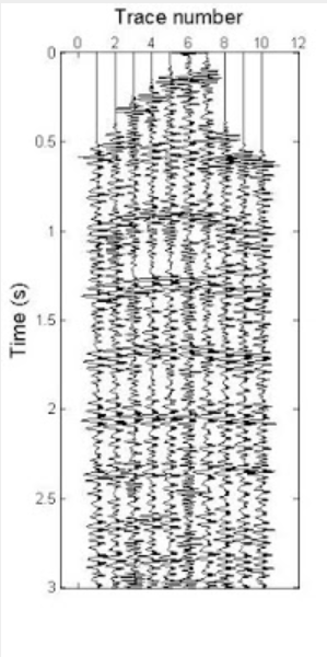
The first figure is the wiggle trace shot gather. After doing the sorting to CMP gathers, velocity analysis and stacking, it can be seen in these six figures (add subtract 1400ft/s) that the data are less chaotic and it starts to show the real image of a subsurface data. NMO correction is also done along the processes after the seismic velocity of layers has been determined, before stacking.
CONCLUSION:
- · All objectives are achieved.
- This lab has shown almost the true figure of the subsurface geology.
No comments:
Post a Comment